Homework - Finite Element Seepage Analysis, Unconfined Conditions
For this exercise, you will build a finite element seepage model of the Lost Lake dam. Start with the base XSLOPE template and modify it to fit the cross section shown below.
Once the input file is complete, upload the file and solve the problem using XSLOPE using the seepage colab notebook:
![]()
The Lost Lake Dam includes a grout curtain, core, shell, riprap, filter, and a drain as shown below.
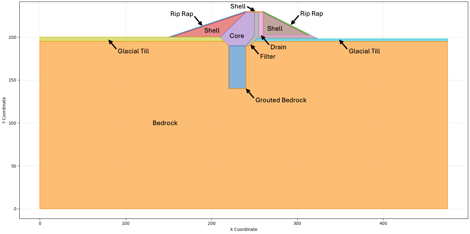
The water is impounded on the left side of the cross section at H = 225 ft. Water seeping out of the right side drains freely.
The material properties are as follows:
| Material | kx [ft/yr] | Ky [ft/yr] |
|---|---|---|
| Core | 0.1 | 0.1 |
| Glacial Till | 4000 | 2000 |
| Bedrock | 2000 | 1000 |
| Rip Rap | 100,000 | 100,000 |
| Shell | 250 | 50 |
| Grouted Bedrock | 250 | 250 |
| Filter | 1000 | 1000 |
| Drain | 10,000 | 10,000 |
For each material, use:
\(\alpha = 0.0\)
\(k_{r0} = 0.0001\)
\(h_0 = -1\)
Use elements that are sufficiently small to capture the details in the thin zones. Select appropriate boundary conditions for the model.
You will need to create your profile lines carefully to ensure that the model is well-posed.
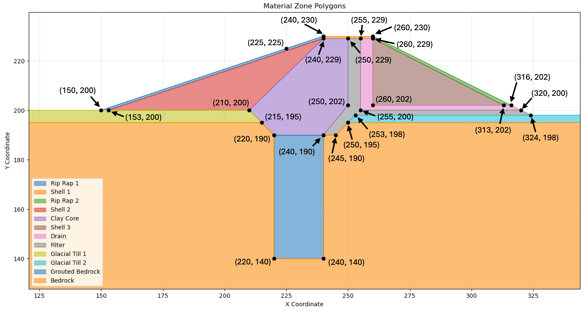
Problem Geometry
The coordinates of the points making up the center part of the cross section are shown below.
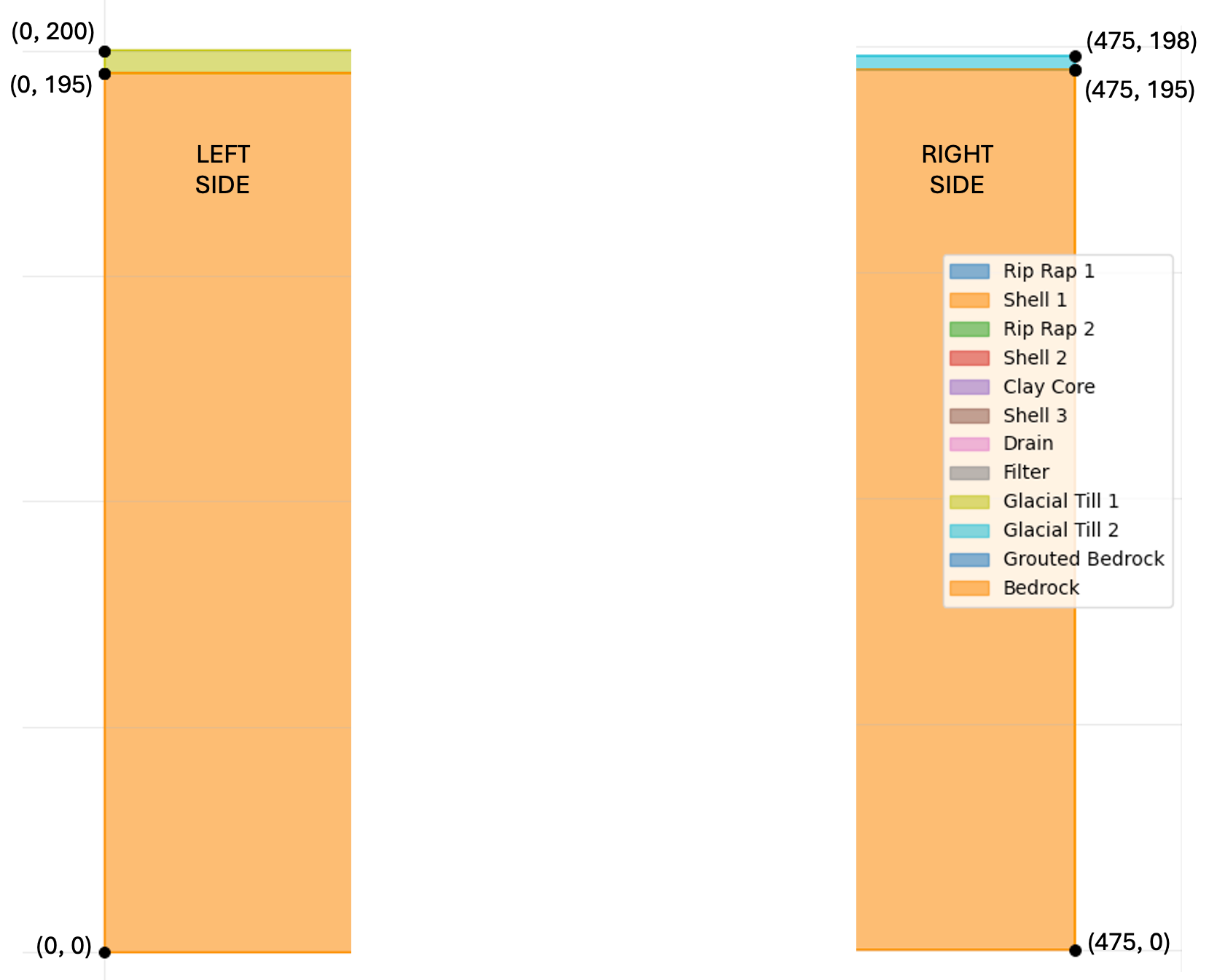
The coordinates of the left and right sides of the cross section are shown below:
Tips
Here are some tips for setting up the problem:
- You only need 8 materials. Use the 8 materials from the list above.
- You will need 12 profile lines. Sometimes multiple profile lines link to the same material. Just enter the material ID at the top of the profile. The name will then appear.
- Make sure you enter the coordinates in the correct order (left to right).
- Profile lines should always be listed from top to bottom. Each line projects down to lower lines to define the regions to be filled in as it creates the polygons. Each line is strictly above all of the subsequent (or at least - not below).
- When you define the profile lines, you only include the line segments on top of the zone. You should not include vertical edges on the left and right ends of the lines. For example, the profile line for the grouted bedrock (blue zone) is only two points. However, you can have vertical lines in the middle of a profile line if necessary - bedrock (orange zone at the bottom) for example.
Submission
Create a PNG of the solution with 25 head contours and use base material = bedrock. Zip up your Excel file and a PNG of the solution plot and upload your zip archive via Learning Suite.
Note
You are allowed to work in pairs on this assignment if you wish. Just copy and upload the assignment when you are done and be sure to make a note who you worked with.
Grading Rubric
| Criteria | Points |
|---|---|
| 12 profile lines created in correct order (top to bottom) | 10 |
| Points on each profile line listed in correct order (left to right) | 2 |
| All 8 materials defined with correct hydraulic conductivity values (kx, ky) | 4 |
| Material parameters (α, kr0, h0) set correctly for all materials | 4 |
| Boundary conditions appropriately selected (H=225 ft left, exit face right) | 6 |
| PNG output shows head contours with base material = bedrock | 4 |
| Total | 30 |